Product Teardown Folding Shelf Bracket
Overview
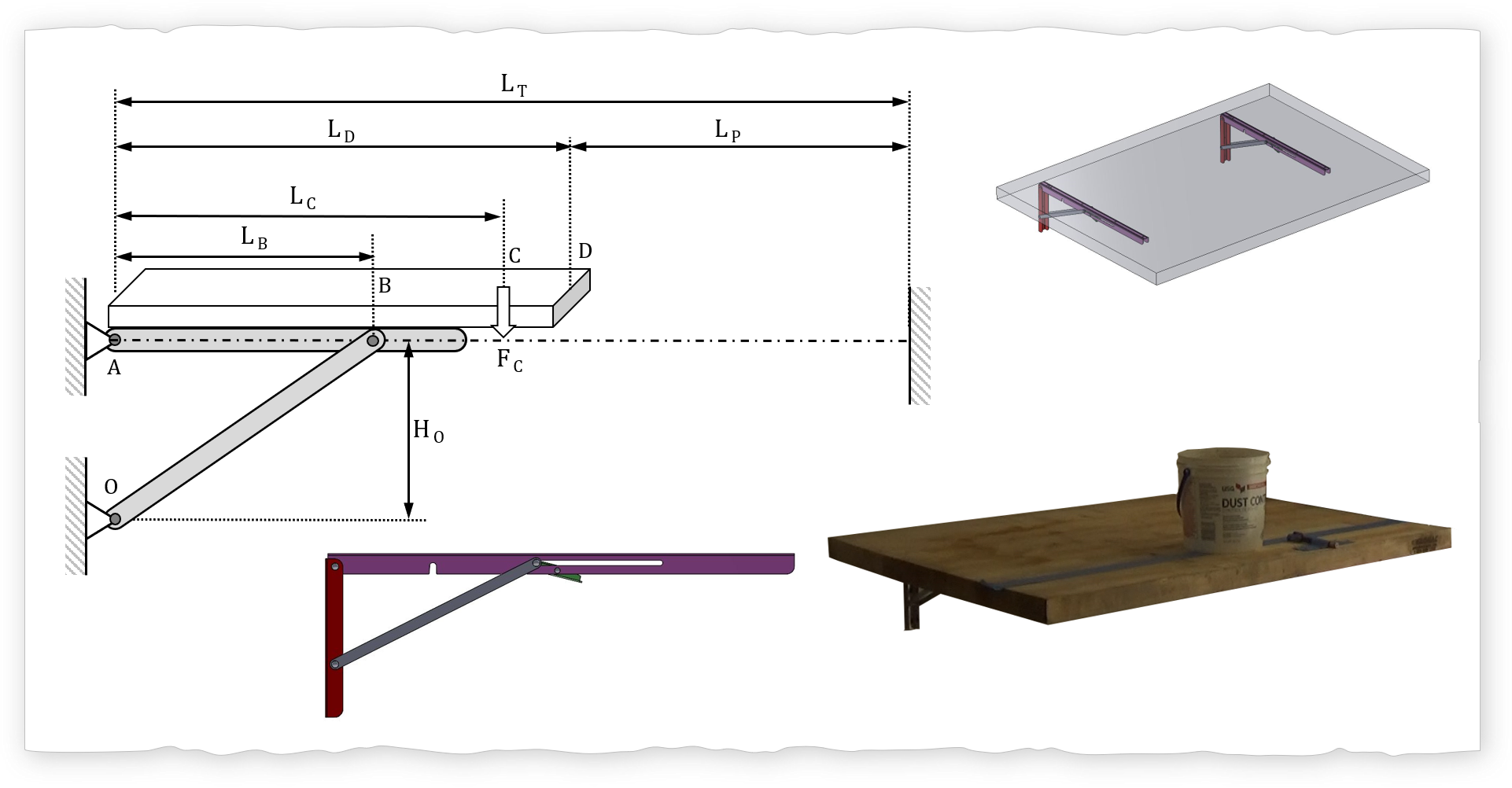
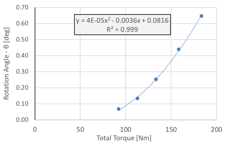
In the deployed configuration the folding shelf bracket can be "modeled" as an overhanging beam with a support (strut). The beam bending analysis along with the Euler buckling analysis demonstrate that buckling will occur (on the support element) at a fraction of the maximum rated loading (placed 10" away from the pivot). Furthermore the Abbe error experiment results show a "softening" of the angular stiffness of the structure which can be explained by the "undesirable" buckling distortion of support element.
Analysis
Abbe Principle
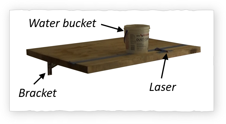
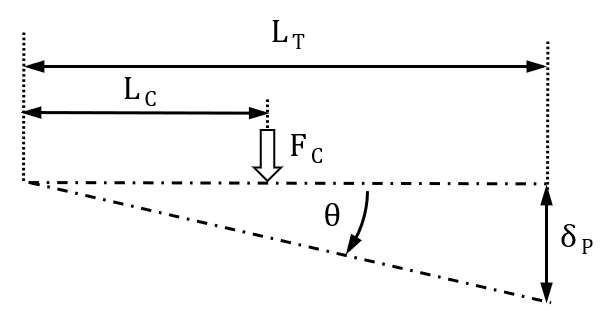
The Abbe principle (Abbe error) is used to measure the angular stiffness \( K_i \) of the folding shelf bracket using the following: laser pointer, mass (variety), length measurement tool. The relationship between the angular stiffness and the moment applied \(M_i\) is: \( M_i = K_i \cdot \theta_i \). The laser is mounted on the table top to project a distance \(L_P\) on to a wall. The applied moment is created by putting a mass on the table at a known length from the pivot hinge (Location A). The projected laser spot will move downwards with the added mass. For this experiment, the mass was increased 35 N (7.8 lbs) to 190 N (42.4 lbs).
Thus: \( K_i = \frac {L_C \cdot F_{C,i}}{tan^{-1}(\delta_{P,i}/L_T)} \)
Small angle approx: \( K_i = \frac {L_C \cdot F_{C,i}}{\delta_{P,i}/L_T} \)
Beam Bending Analysis
The beam bending problem can be solved by first creating a free body diagram and keeping in mind two things: 1) each node is in equilibrium, and 2) each element is in equilibrium. The goal is to determine the axial force \( F_{crit} \) (compressive force) on the support element and compare it to the Euler buckling force \( F_{buckle}\). If the axial force is greater than the buckling force then the support is buckling and the table will have an additional undesired tilt.
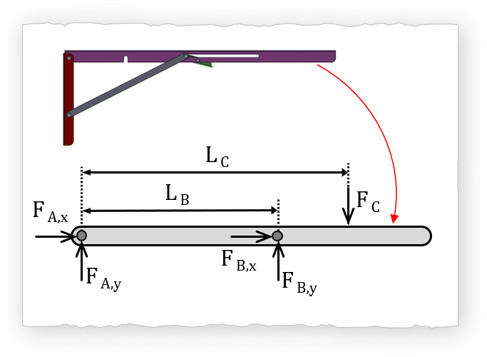 $$ \sum M_A=0 $$
Thus: \( L_B \cdot F_{B,y} - L_C \cdot F_C = 0 \)
$$ F_{B,y} = F_C \cdot \frac {L_C}{L_B} $$ $$ \sum F_y=0 $$Thus: \( F_{A,y}+F_{B,y}-F_{C} \)
$$ F_{A,y} = F_C \cdot \left ( 1 - \frac {L_C}{L_B} \right ) $$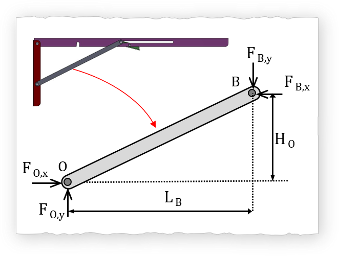 $$ \sum M_O=0 $$
Thus: \( H_O \cdot F_{B,x} - L_B \cdot F_{B,y} = 0 \)
$$ F_{B,x} = F_{B,y} \cdot \left ( \frac {L_B}{H_O} \right ) $$ $$ F_{B,x} = F_C \cdot \left ( \frac {L_C}{H_O} \right ) $$Euler Buckling
The calculated buckling force \( F_{buckle}\) given the geometry of the support is approximately 375 N. Given L = 240mm, E = 190GPa, and cross section ~ 11.5mm x 2.3mm geometry. The end restraint coefficient is C=1 since both ends are pinned.
Where: \( k_{gyration} = \sqrt { I/A} \)
Where: \( I = \frac{1}{12}b \cdot h^3 \)

Analysis: Find \(L_{critical}\)
\(L_{critical}\) is the maximum distance from the wall that the center of mass (advertised 500 lb) can be placed without buckling. Note that \(F_{total}\) (refers to the total load) since the equation accounts for the number of links \(N_{Links} \).
Then Solve for \( L_c\),
$$ L_c = \frac { \pi^2 \cdot E \cdot w_{link} \cdot t_{link}^3 \cdot N_{links} }{12 \cdot C^2 \cdot L_{link}^2 \cdot F_{total} \cdot \sqrt{ \frac{1}{H_O^{2}} + \frac{1}{ L_B^{2}}} } $$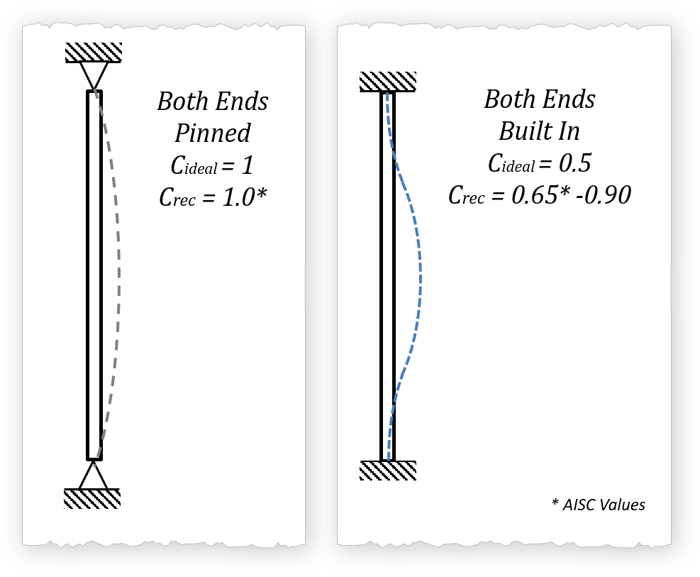
The results are a little surprising. The only way that the pair of folding bracket shelf can be used to hold 500 lb is that if the center of mass of the 500 lb is 2.56 inches (65 mm) from the wall, per the analysis where the both ends are pinned (C=1). Even in we were to assume that both ends are built in (which I personally believe is a wrong assumption given the geometry and Saint Venant's principle of characteristic dimensions), the critical length is 6.06 inches from the wall (154 mm). The analysis does not take into account eccentric loading which further reduces the loading capacity. Now at 10 inches (254 mm) from the wall the most that I would be willing to comfortably add without buckling is 128 lbs (567 N). The table outlines the findings of the buckling analysis.
Parameter |
Both Ends Pinned (C=1) |
Both Ends Built in (C=0.65) |
|---|---|---|
Link (support element) Buckling Force |
374 N 84 lb |
883 N 199 lb |
\(L_{critical}\) |
65 mm 2.56 in |
154 mm 6.06 in |
Fix \(L_{critical}\) |
||
\(L_{c}\) = 254 mm 10 in |
567 N 128 lb |
1343 N 302 lb |
\(L_{c}\) = 381 mm 15 in |
380 N 85.4 lb |
900 N 202 lb |
Results
Measurements
Below is the plot that will give you the tilt angle as a function of the total applied torque (Nm).
Tips
I have 1,001 references and yet I only need one. Make sure that you understand three things: 1) equation, 2) limitations, 3) implications. Using multiple references is ok as long as you understand the concept. Be MEGA!!! careful with units especially when working in teams. One trick is to put the units in the variable when coding. For example "power_watts" or "power_kw" when naming the variables. Also some equations have an expected unit. For example the hydraulic power equations: in metric units: Hydraulic Power = \( \Delta P_{kPa} \cdot \dot{V}_{m^3/s} \); now in imperial units: Hydraulic Power =\( \frac{\Delta P_{psi} \cdot \dot{V}_{ft^3/s} }{3.819}\). Just for reference \( \Delta P \) is the pressure difference, and \( \dot{V} \) is the volumetric flow rate. Fun BBC article on miscalculations... Oooops...
Buckling References
Units, Units, & Units
Miscommunications happen. Just look up three words...
References
Euler Buckling
DARE2MAKE CHALLENGE
Find Your Passion
Invest in Education & Growth
Make Something Amazing
Schedule
- Overview Meche PE
- Product Dev. Process
- Explore → Hands On
- I - Principles
- → Foundation
- → A - Basic Engineering Practices
- → B - Engineering Science and Mechanics
- → C - Material Properties
- → D - Strength of Materials
- → E - Vibration
- II - Applications
- → A - Mechanical Components
- → B - Joints and Fasteners
- → C - Supportive Knowledge
- III - Holistic Knowledge
- → A - Heat Transfer
- → B - Fluid Dynamics
- → C - Controls
- → D - Thermodynamics
- → E - Electronics
- IIII - Precision Machine
- → A - Error Apportionment
- → B - Metrology