Product Explore CNC Router MillIE
Overview -
CNC machines are part of the core foundation of our manufacturing infrastructure. For any economy, to embrace its manufacturing capabilities it's workforce should appreciate the foundation and complexities of what it takes to bring products to our homes. I selected this product because the company is based in the US and they try to make things in the US (outsources some components) and it looked pretty good based on the website for my purpose. What is my goal?: Share the Art, Beauty, and Intricacies of Precision Machine Design. The best way that I saw doing so is by sharing how I see components interconnected to create a beautiful painting and a work of art. Like Leonardo da Vinci we must pay attention to the little things and our foundations. We should grow in love with this overtime just like we do with the people around us. The mnemonic device that I created for the Art of Machine Design is: AAMMOR. A play on words with a very special word in Spanish: Love. AAMMOR stands for the following: Analysis, Assembly, Manufacturing, Methodology, Objectivity, and Respect. Let's dive in with some love for making things.
Observations
Assembly
Manufacturing
Methodology
Objectivity
Respect
Upgrades
Save $: Reduce # parts
Save Space: Move Y Axis Cable Management System
SAFETY: ROUTER MOTOR OFF!
Simplify: Limit Switches Mountings
Clean: Exit wire guide
Currently Working On:
Analysis (linear motion guides, motor life)
Measurement & Instrumentation
XBox Controller Interface
References
Observations
Assembly
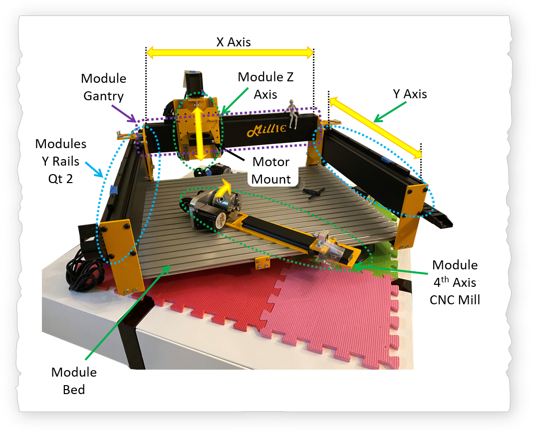
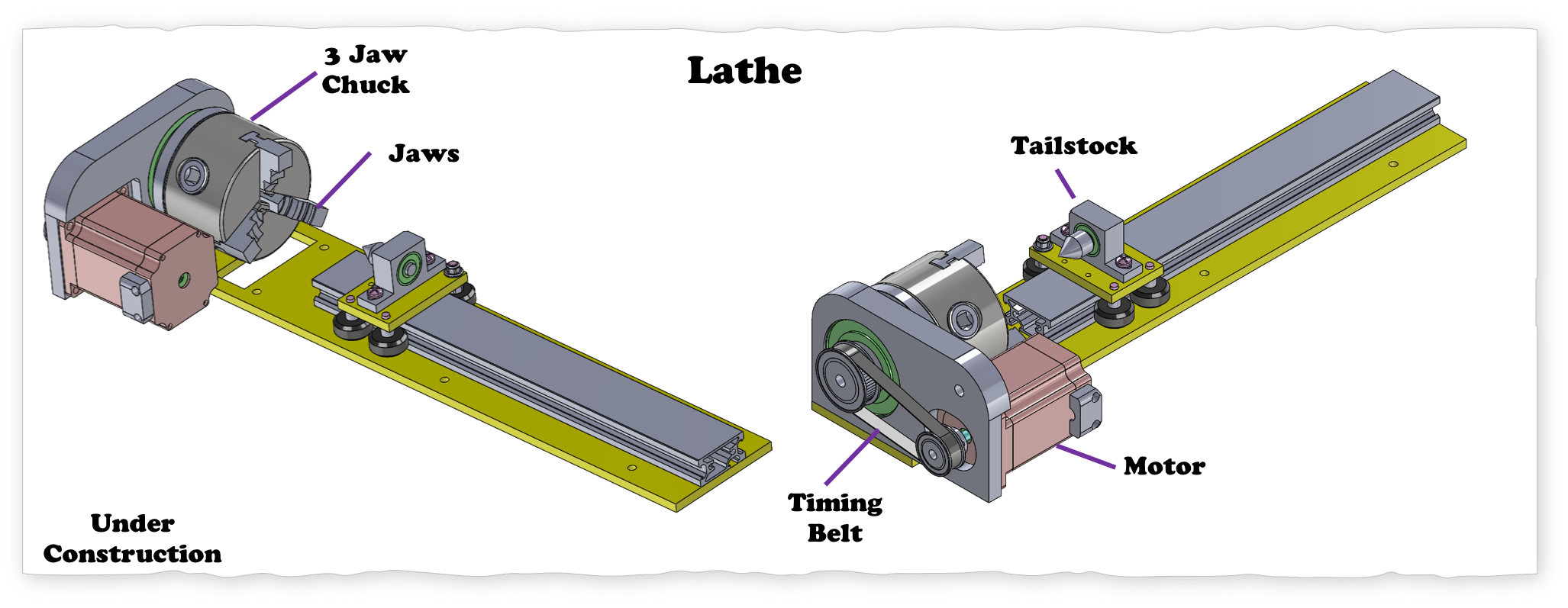
This CNC router or gantry mill (Millie) is one large assembly made up several sub-assemblies. It is a gantry router. Primarily designed for cutting: "Mills wood, plastic, foam, carbon fiber, circuit boards, soft metals, and can make occasional light cuts in hard metals." Millie has at least 5 modules: Z axis, X gantry, Y axis, dewalt router (not shown below), and the controls module. There is also an option to have a turning module that will allow the unit to become a little mini lathe.
Manufacturing
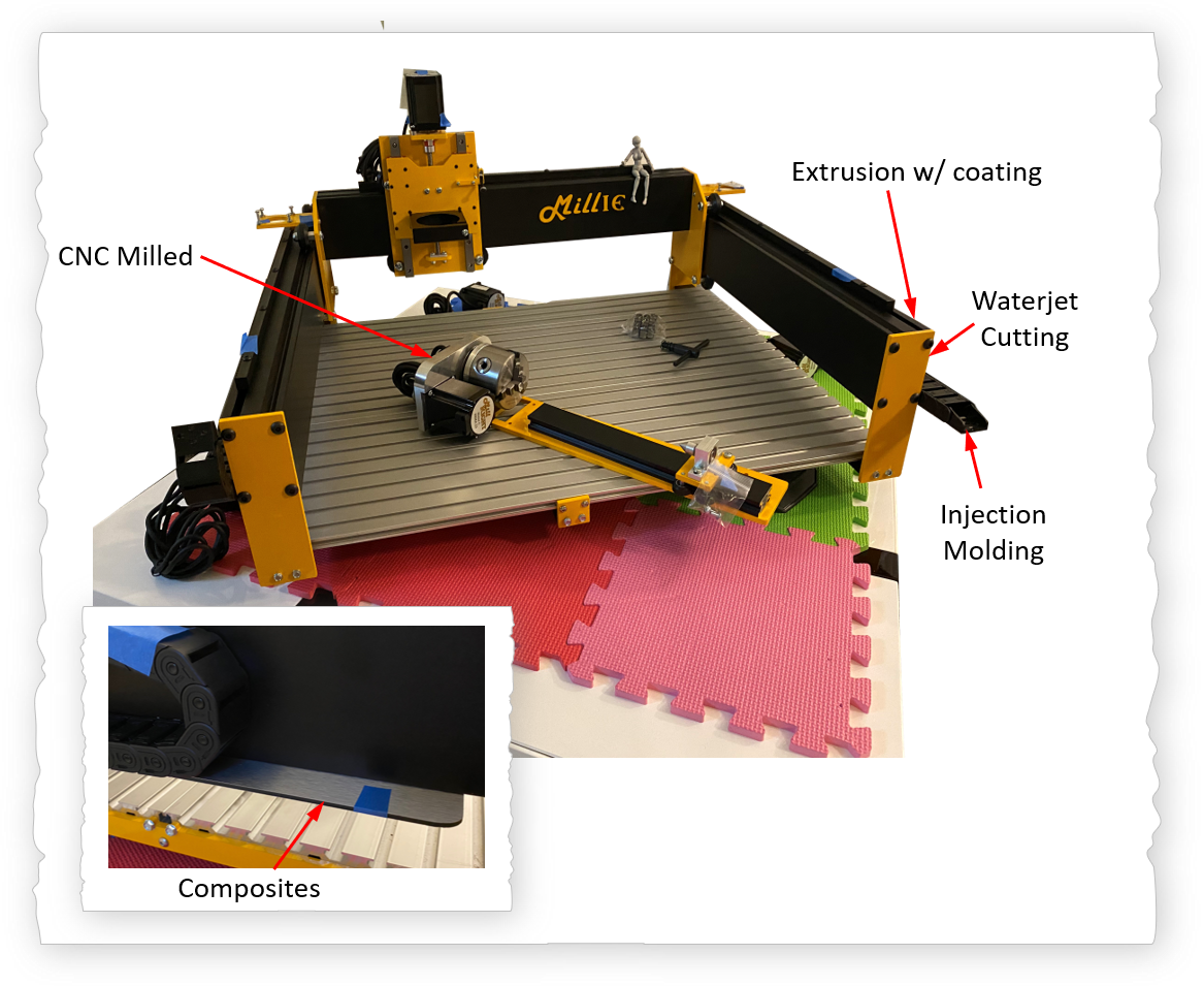
Millie is made up of an array of parts manufactured in at least five ways: 1) Waterjetting: The yellow plates appear to be waterjetted based on the edge surface even after the coating, those features are still visible. 2) Aluminum extrusion: The bed of the router is composed of three extruded plates. The two long channels of the y axis (shown in black) as well as the gantry (shown in black) are also composed of extruded aluminum components. 3) CNC Milling: The forth axis (cnc lathe part) has an aluminum vertical mounting plate that has been CNC milled. 4) Injection molding: The wire guides to minimize wire entanglement are made using injection molding. And 5) Composites: The plates bellow the wire guides are made of a sandwich of materials. Mmmmmmm, like those little ice cream sandwiches.
Methodology
How we do things matter! In assembly, parts design, manufacturing, drawings, gdnt, etc. the details matter. While assembling this machine I found that a couple of things that I would do differently based on my experience design for assembly. A subpage will be created for the details on the assembly. There are many ways to complete a journey. Link to be added soon.
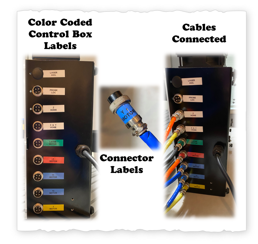
It is much easier to organize and label wiring during the assembly process. The connections are both color coded and labeled; thus, it is easy to see where wires are connected and reduce the chances of "Ooooppps."
Objectivity
The market for this cnc router machine is for hobby enthusiast and prototyping RnD, etc. The manufacturer is a small company that produces these affordable units. The topics that I am going to discuss and share are intended for precision machines, thus this is only intended for educational purposes only. Summary: Play Nice. Let's keep things in context.
Opportunities to Improve
T plate clamps set will not work across the interface of the aluminum extrusion.
Respect: Machine Design Principles
Thread Engagement
In two different modules, I noticed that the thread engagements between the screw and the "nut" was about 3 threads or less. Note that the first three threads carry 72% of the load, thus in general it is good practice to ensure more than three threads are fully engaged.
Short 4 min Video
Spur Gear Mounting
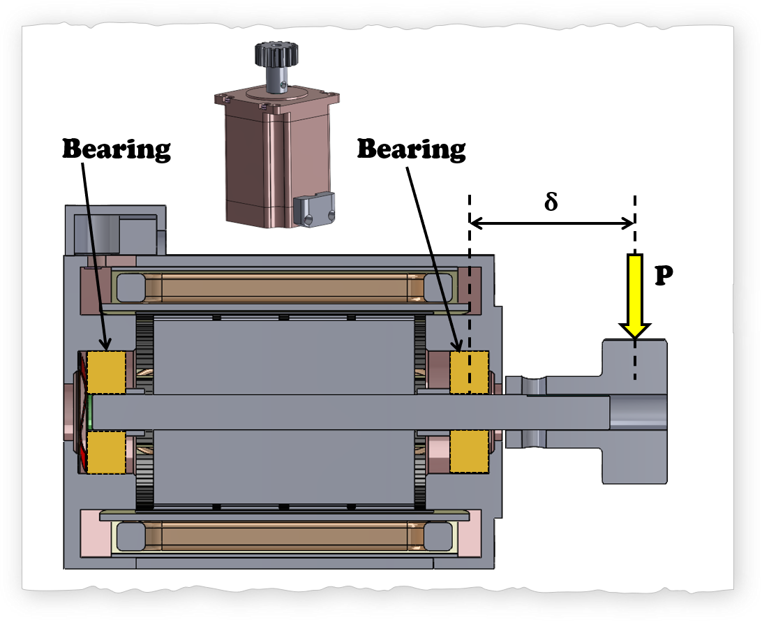
For precision machines, one quick tip is to place the loading as close to the bearing as possible. As \( \delta \) increases the bearing life of the motors decreases. Early in the design stage it is good to keep this tip in mind.
Upgrades
Occam's Razor: KISS = KEEP IT SUPER SIMPLE. When I assemble a machine and even more when I design a machine, I try to keep it to the minimum number of parts, and optimize the space. While building Millie (CNC router), I first assembled the machine how the manufacturer specifies (this is really important). It was only after assembling the machine and understanding all of the intricacies that I am able to suggest upgrades.
Goals of Upgrades
Short 3 min Video
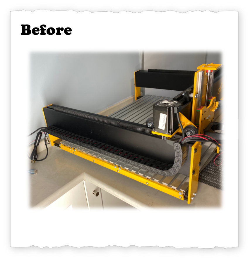
#1 Reduce Parts: Save Cable System & Composite
Upgrade 1: I noticed that since the motors for the y-axis moves with the gantry, I can remove one Igus cable system from the motor on the right by simply running the cable inside the gantry. Doing so saves us the use of one composite panel, and one Igus cable management system. The width of the machine thus reduces from 35.0" to under 34.5". Temporarily, I'm running the right y-motor cable on top of the gantry. Eventually I'm going to be running the motor cable through the center of the gantry extrusion. Since, I intend to also upgrade the motor holders to reduce the loading on the motors bearings (thus increasing motor life), I'm going to wait before drilling a hole into the side plates of the gantry.
Short 3 min Video
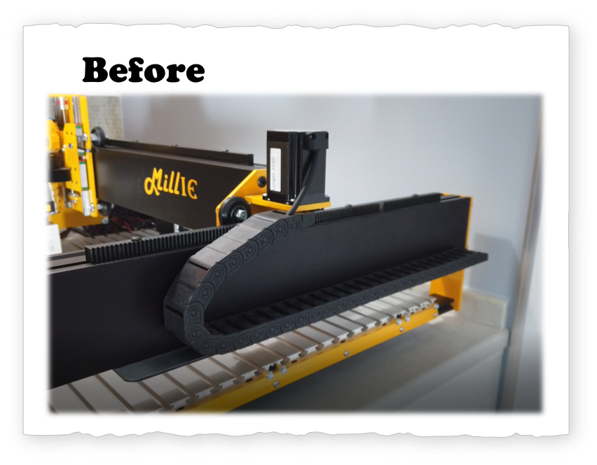
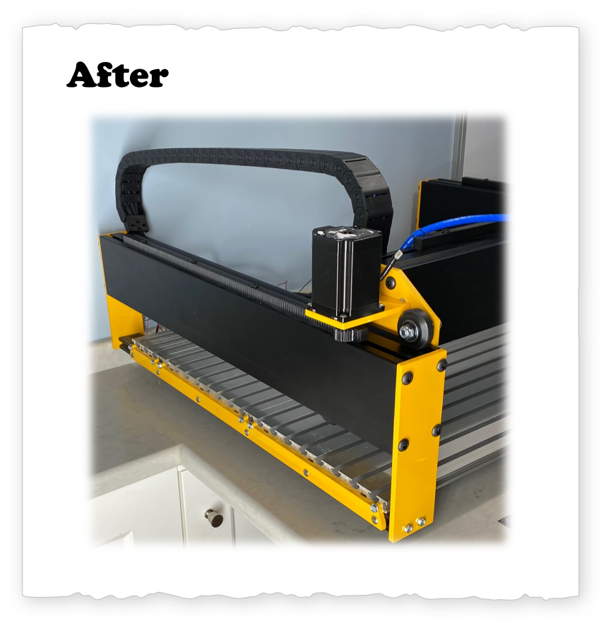
#2 Reduce Space: Move Y-axis cable management
Upgrade 2: In the spirit to getting a more compact design. I tried to consolidate cable management system for the y-axis on the left motor. I did the thought experiment of having an array of these machines for production (Let's say 3 units wide and 5 units high). Thus, I would like to be able to pack these machines one next to the other with minimal space in between. So I looked at putting the y-axis cable management system inside the width of the machine. At the same time I tried to lower the cost by reducing the number of parts. I was able to put the cable management system inside the gantry space with zero interference to the operations. The alterations to the y-axis cable management system has reduced the effective width to 33.75 inches. The y-axis stepper motor mounts will also be eventually replaced to further remove the width of the machine from 33.75" inches to 31.75". Thus, at the end of the y-axis modifications the machine will have a 9.3% improvement in space reduction (3.25"/35.00").
#3 SAFETY!!!: Router Motor Emergency OFF!
ALSO DO NOT WORK ON ELECTRICAL EQUIPMENT WITHOUT TRAINING.
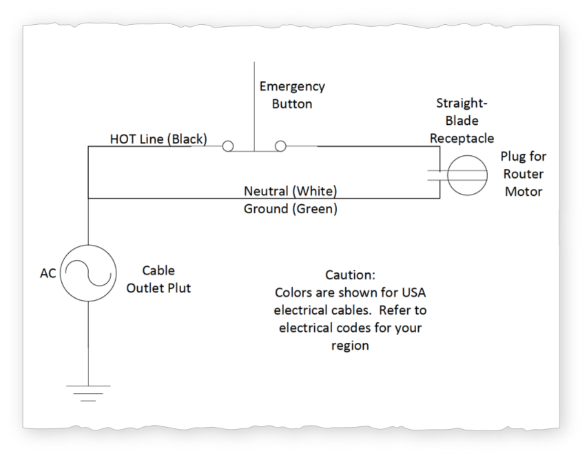
Upgrade 3: While the first 2 upgrades are cosmetic in nature, I consider the third upgrade a MUST!!! This is an upgrade I have suggested to the manufacturer of the unit. Currently the "push button" that turns off the unit is not labeled as an "emergency button." The existing red push button on the control box turns off the power to the drive motors; however, the router with cutting tool continue to SPIN!!!! (ahhhhhh). Thus if you see someone about to get hurt, by putting their hand close to the tool and you hit the "Power Off" button, that person can still get HURT!
As an instructor in a machine shop, someone getting hurt is SCARY! The upgrade consists of turning the "push button" to an "emergency shut off button" that turns off the entire machine! I started to explore how to do it.
Diagram
Video
Coming Soon.
The "Emergency Off" modification goes into modifying the existing emergency off button, getting a straight-blade receptacle, and a three prong 10 amp cable. The overall cost for the modification is on the order of $10.
Emergency Button Modification
The existing emergency button is configured that when pressed the red side gets disconnected and the green side gets connected. If you search online this is labeled as "1NO 1NC DPST switch equipment." I ordered a pair from online of the ToTo Emergency Stop Push Button exactly the same one that the existing unit. I then changed the little metal sections pieces under the unused "green cap" to turn it equivalent to the Red.
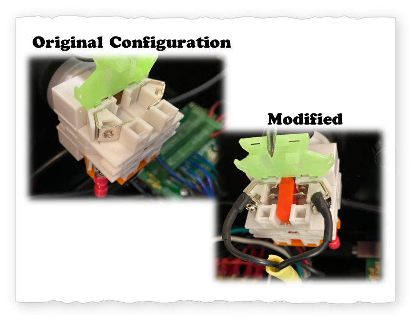
The replacement components are from the unit purchased.
Straight Blade Receptacle
I found a 125V 15 Amp panel-mount straight-blade receptacle in McMaster for $1.57. Since it was going to cost more in shipping then the receptacle I decided to instead harvest one from an old cup power holder (you don't always need to buy something, just re-purpose). Making the hole in the steel control housing structure is dangerous and requires finesse. Metal chips getting into the power supply, micro-controller, or the motor drivers will quickly fry the entire unit. One way to do it is to put silly putty underneath, while also providing suction from above.
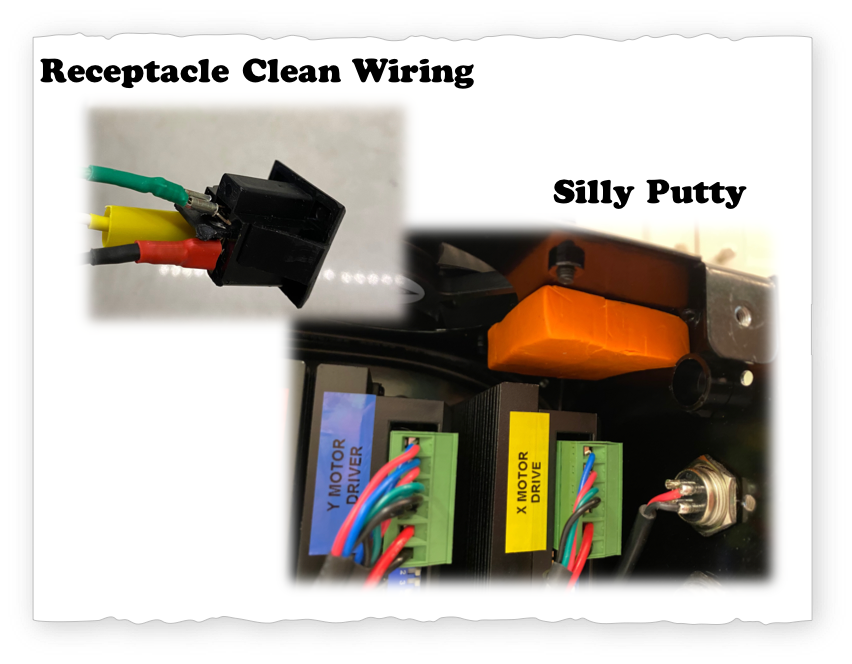
Quick Connect terminal spade were soldered and heat shrinked.
Secondary Outlet Plug
So I installed a second outlet cable for the auxiliary device (aka router motor). While I most likely could have used power from the existing power cable that goes to the power supplies, I did not want to risk something going wrong and burning up drivers accidentally from the power demands of the router. FUNNY things can happen when we don't know all of the wiring details or power requirements. So move forward CAREFULLY, with safety systems in place.
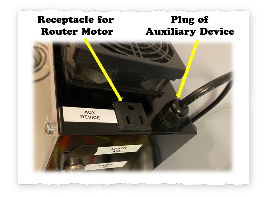
I used a Nylon cord grip cable gland to strain relief the electrical cable.
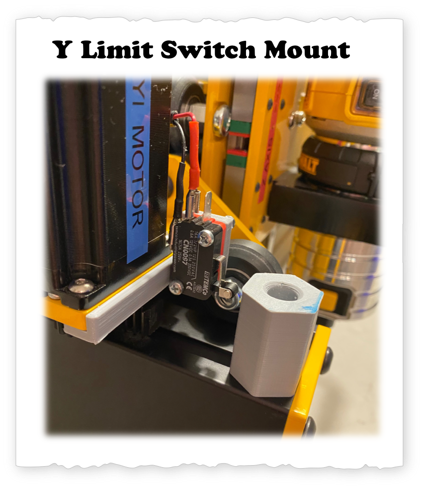
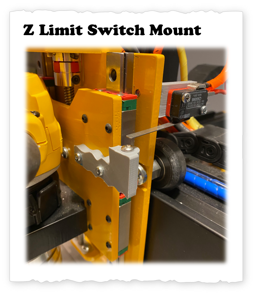
#4 Simplify Limit Switch Mounting
Upgrade 4: When I saw the number of parts to mount the limit switches, I just thought: "why don't I just 3D print a little bracket for the switch itself and one for the post. It took a little bit of brain storming...
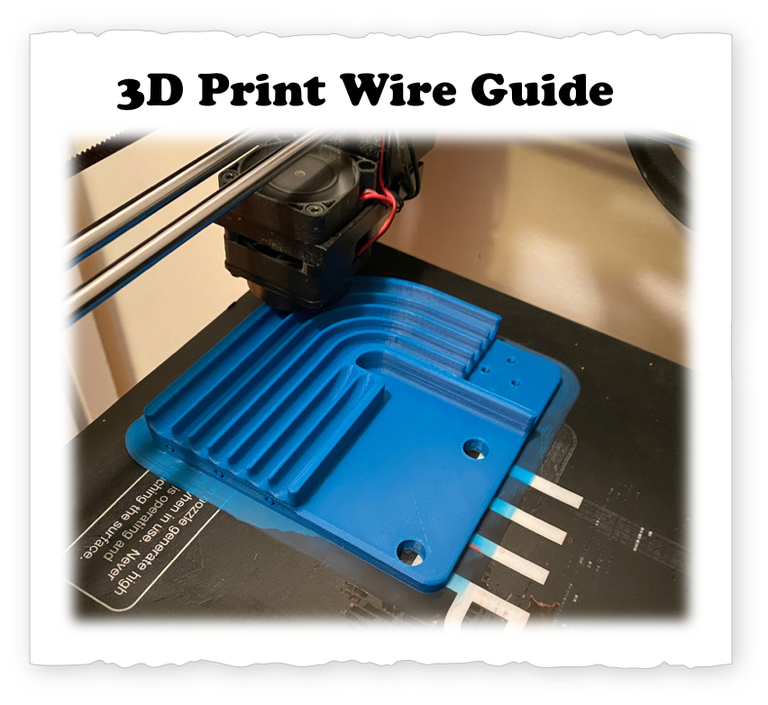
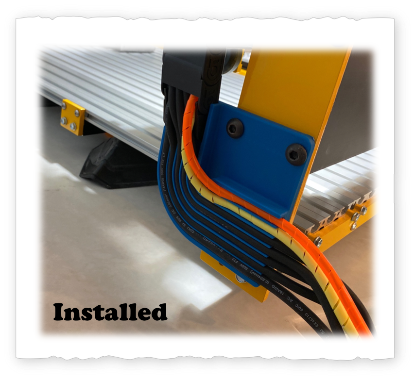
#5 Wire Guides
There is something about having a bundle of wires exiting a wire guide that makes me smile. I always think: "make it pretty and clean." In the process of moving the Y axis cable management system I also decided to clean up the wires as they exit the cable management system. The 3D plastic piece is mounted to the machine via two screws that are already part of the machine.
Home Machine
UGS - Homing
Homing Sequence
Setup Wizard
Configure Home Switches
lathe Module
DARE2MAKE CHALLENGE
Find Your Passion
Invest in Education & Growth
Make Something Amazing
Schedule
- Overview Meche PE
- Product Dev. Process
- Explore → Hands On
- I - Principles
- → Foundation
- → A - Basic Engineering Practices
- → B - Engineering Science and Mechanics
- → C - Material Properties
- → D - Strength of Materials
- → E - Vibration
- II - Applications
- → A - Mechanical Components
- → B - Joints and Fasteners
- → C - Supportive Knowledge
- III - Holistic Knowledge
- → A - Heat Transfer
- → B - Fluid Dynamics
- → C - Controls
- → D - Thermodynamics
- → E - Electronics
- IIII - Precision Machine
- → A - Error Apportionment
- → B - Metrology