Product Tear-down VonsShef
Overview
I believe the VonShef mixer was a great example how much we can learn from an everyday home product when we engage our curiosity and start asking: Why!, How!, huhhh that looks different!, or that is interesting! As the process evolves you get more and more depth and understanding about how machines work.

Observations
Housing
Wiring Diagram
Design for Assembly
Machine Design Principles and Practices
Measurements
Transmission Ratio
Angular Velocity
Vertical Velocity to Raise Mass
Analysis
Motor Sizing
Helical Compression Springs
Hertz Contact
Tips
References
Observations
Housing
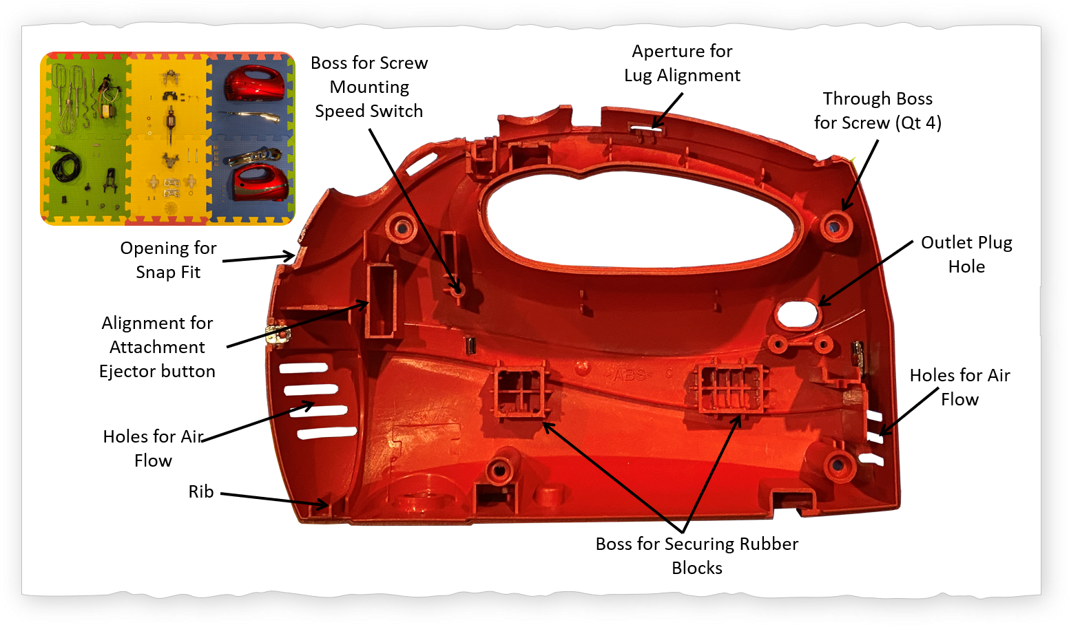
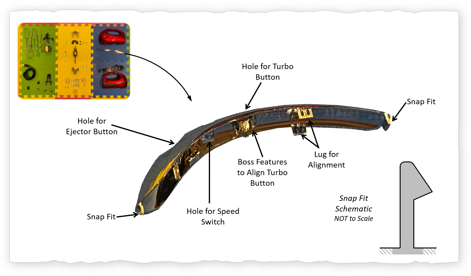
The housing consists for 5 injection molded pieces: 2 half shells, 1 top cap, and 2 aesthetic side pieces. Each half shell has pockets to hold two elastomer blocks that are used to constraint the internal motor assembly. The half shells align using 4 raised boss features with an internal chamfer section for initial rough alignment, and secured to each other using 4 screws. The top cap is aligned using a pair of "lugs" and held to the rest of the housing via snap-fits. The motor sub-assembly is held inside the housing structure using four elastomer blocks. Note that the general rule of thumb is to have the thickness of the ribs and structural bosses to be between 40% and 60% of the wall thickness
Quick Wiring Diagram
Below is the diagram how components are wired together inside the mixer. Future work with a blender most likely I may cover how AC motors work and the transformer speed control switch. For the time being, a friend suggested to add relevant patent. US Pat: 4,935,678
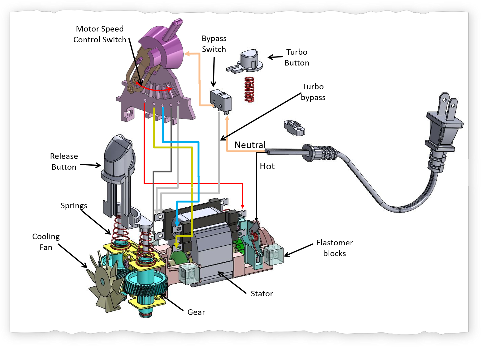
The cable from the outlet plug is secured to the inside of the housing using an injection molded piece of plastic clamping down on the cable via two screws. The hot line goes to the back of the motor where it soldered to the terminal on the commutator brushes holder. The neutral line goes to a bypass switch for the turbo button. When the turbo button is pressed down the turbo bypass line is active and the motor goes into the highest speed; otherwise, the velocity is controlled via the motor speed control switch. The motor speed control switch provides an auditory click feedback to the user. There are groups of people that focus on auditory feedback in consumer products. Think of the click sound as feedback to the user of a changing speed.
Design for Assembly
The total number of parts = 84 (Attachments included). It was a little bit of a challenge assembling the top cap at the end of the assembly the first time. The unit may be assembled using a fixture, or they found a trick to do it quickly which I found by the third time I assembled it (reciprocity is the answer). It is interesting to see that four elastomer blocks constraint the motor assembly inside the housing. From the safety standpoint the knob of the speed control switch has a raised feature that prevents the release button from being pushed (hence ejecting the rotating elements) while the unit is operating.
Machine Design Principles & Practices
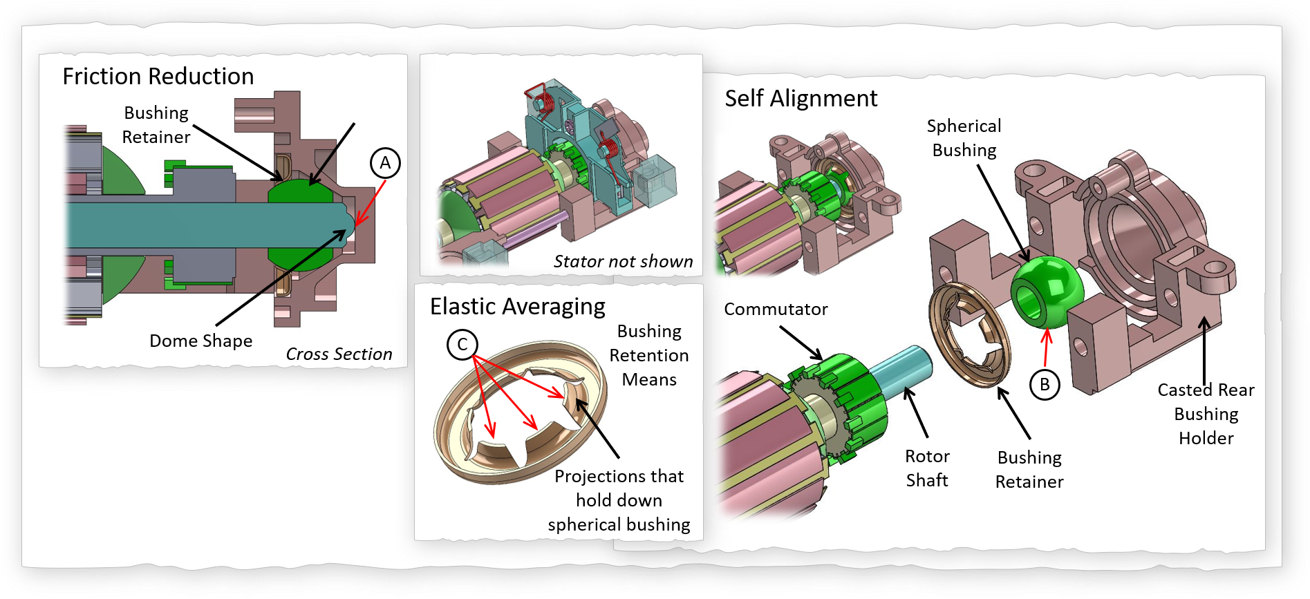
This kitchen mixer has at least three good implementations of machine design principles/practices: 1) friction reduction, 2) self alignment, and 3) elastic averaging. The dome shape (label A) towards the rear of the rotor shaft is to support the axial loads of the rotor with minimal friction. Since torque is proportional to the the radius, by making the radius effectively zero, the axial force produces the minimal friction as the rotor spins. The spherical bushing (label B) used to hold the shaft allows for self alignment of the shafts to the rotor. Any manufacturing variations (within the tolerances) should be accommodated by self alignment configuration. The mounting of the spherical bushings to the casted metal structure is a great example of elastic averaging. The stamped metal (label C) plate has 6 projections that constrain the spherical bushing evenly while still allowing for the spherical bushing to be adjusted for alignment variations during the initial assembly.
Measurements
Transmission Ratio
The measured transmission ratio is 21.5. The theoretical transmission ratio based on equations for a worm drive transmission system derived below is 21.8. The dimensions used to calculate the theoretical transmission ratio from the CAD are located below: The lead is 4.57 mm and the diameter of the follower gear (driven gear) is 31.7 mm.
Worm Drive
The transmission for a worm drive is
$$ TR = \frac{2 \cdot \pi}{\theta}$$where \(\theta\) can geometrically be defined by
$$ \theta = \frac {l_{lead}}{\frac{D_f}{2}}$$thus the transmission ratio in terms of the lead and the follower gear diameter \(D_f\) is
$$ TR_{worm} = \frac{\pi \cdot D_f}{l_{lead}} $$ID Terms
Angular Velocity
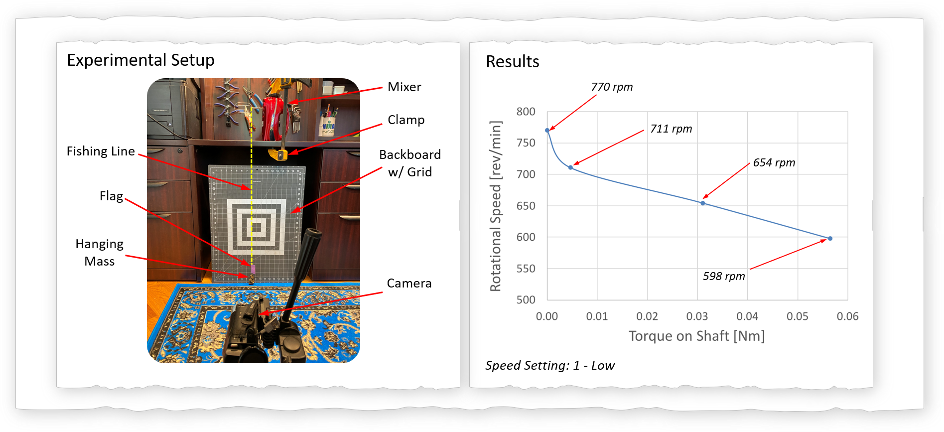
The angular velocity at the lowest speed setting was measured between 720 rpm and 780 rpm using a video recording, and 770 rpm using a tachometer (Uni-T 5URH0). The angular velocity at the highest speed setting using a slow motion video recording was 1140 rpm, and 1150 rpm using a tachometer.
Vertical Velocity to Raise Mass
A video recording is fabulous for gathering information. For example, I used a camera to record the velocity to raise a known mass. If I know the weight of the mass then I can calculate the power required to move the mass from location A to location B. Note that the results show that as the torque on the shaft increases (done by hanging a heavier mass) the rotational speed (rpm) decreases. If we keep doing this experiment eventually we will get to the stall torque of the motor. I will leave that for when I take apart the drill.
Analysis
Motor Sizing
The goal is to relate the motor power to the electro magnetic shear stress (average air gap shear stress), \( \tau\). This will help us in the future to rapidly size motors based on power. For a more in depth explanation (down the rabbit hole) see 6.685 Electric Machines by Prof. James Kirtley.
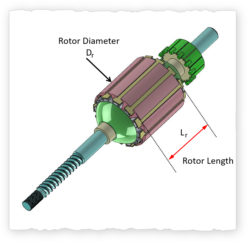
Rotor Geometry
Finding \( \tau \)
$$ Power = \tau \cdot A_{SA} \cdot \tfrac{D_r}{2} \cdot \omega_{free} $$Where the effective surface area of the rotor is
\(A_{SA} = \pi \cdot D_r \cdot L_r \)
Thus, the electromagnetic shear stress is:
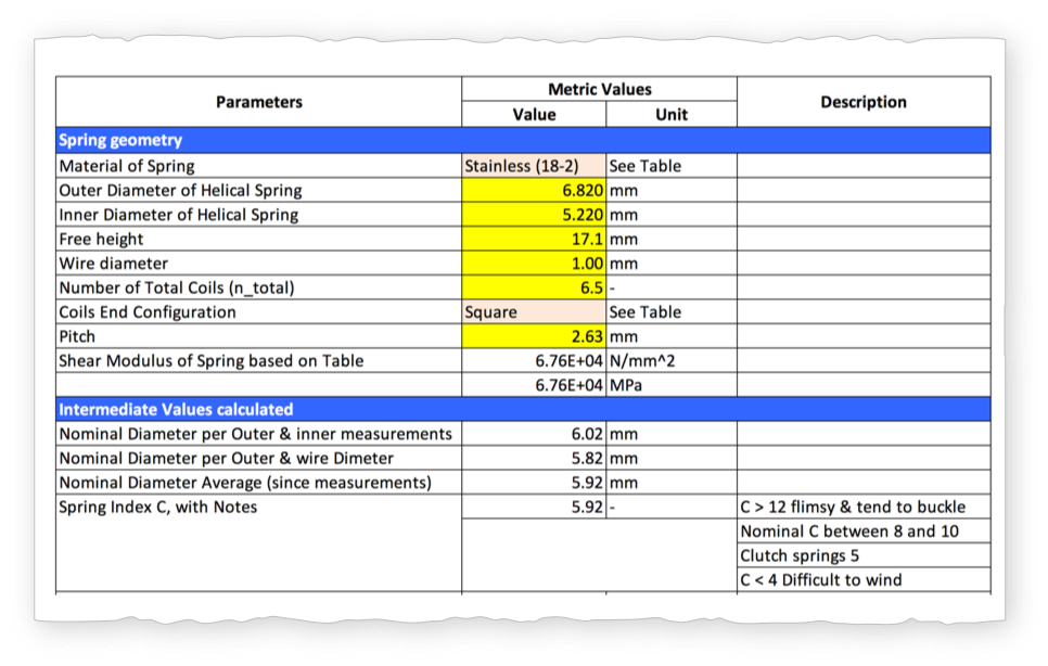
Helical compression springs
An fea analysis of a compression spring magnifies the buckling effect of long compression springs. This is why I am in favor of using engineering equations to determine the performance of helical compression springs. The helical compression spring excel allows for rapid spring sizing and changing materials to quickly converge on a design.
Spring FEA

Springs Excel
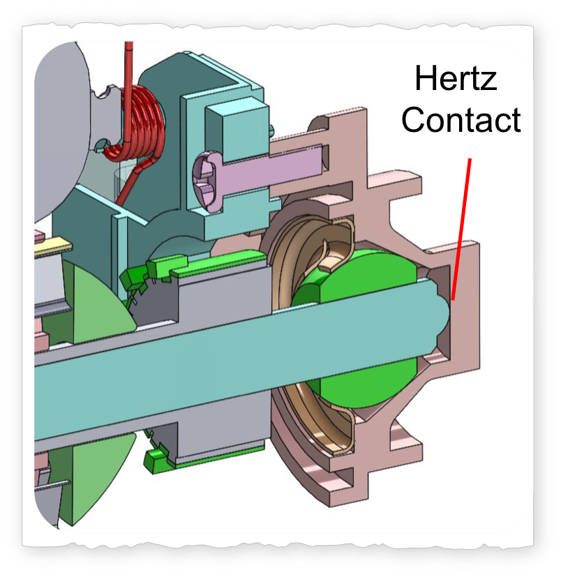
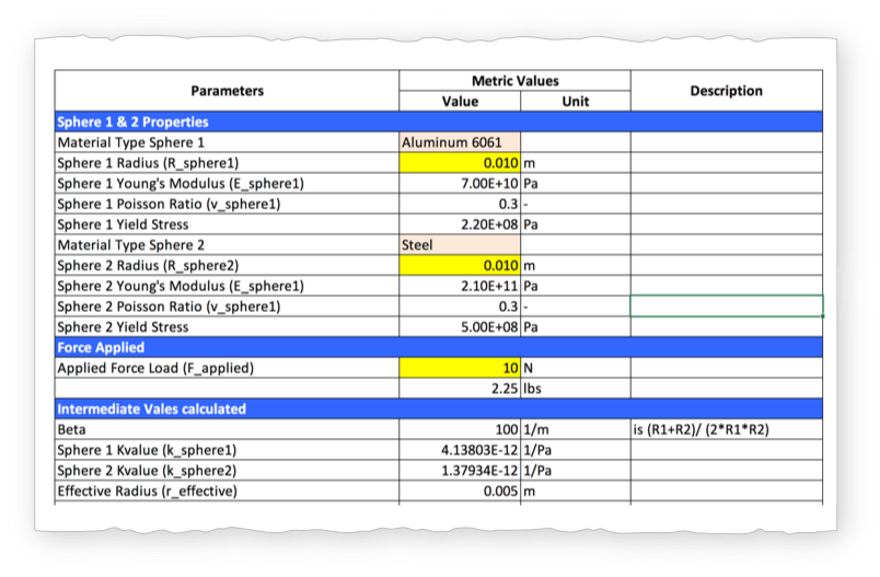
Hertz Contact
The static contact (not rotating) between the dome end of the shaft to the bearing housing flat section can serve as an example of hertz contact between a sphere and a flat surface. In the VonShef example the dome shape feature serves to axially constraint the rotor shaft in a way that it reduces friction while rotating.
Hertz Excel
Tips
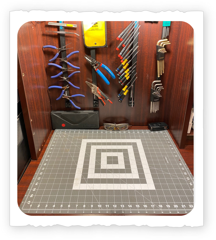
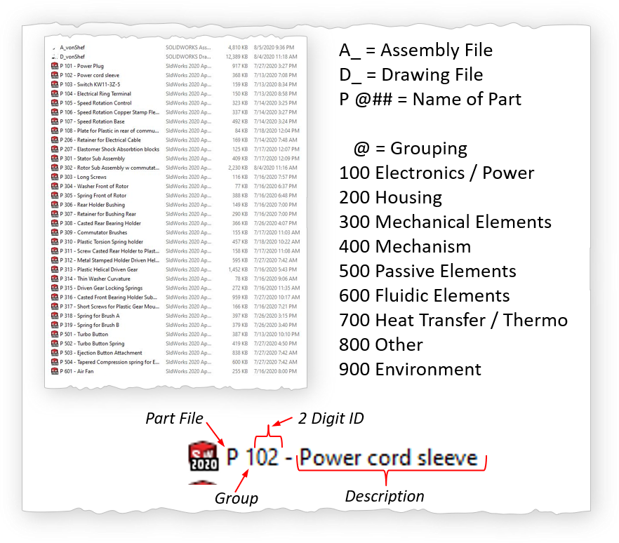
The most valuable tip for doing a tear-down or take apart or anything with engineering is: cleanliness. The tools region should be clean, in the long term it will speed things up because you will know exactly the location of a particular tool. Similarly to organizing the physical areas one must also organize digital files. The name structure of digital files is VERY important. Imagine coming back in 15 years to get a file from an old hard drive. The name structure should help you to quickly find information.
Keep Tool Area Clean
Organize CAD Files
References
Worm Gears
Helical Gears
Compression Springs
Hertz Contact
DARE2MAKE CHALLENGE
Find Your Passion
Invest in Education & Growth
Make Something Amazing
Schedule
- Overview Meche PE
- Product Dev. Process
- Explore → Hands On
- I - Principles
- → Foundation
- → A - Basic Engineering Practices
- → B - Engineering Science and Mechanics
- → C - Material Properties
- → D - Strength of Materials
- → E - Vibration
- II - Applications
- → A - Mechanical Components
- → B - Joints and Fasteners
- → C - Supportive Knowledge
- III - Holistic Knowledge
- → A - Heat Transfer
- → B - Fluid Dynamics
- → C - Controls
- → D - Thermodynamics
- → E - Electronics
- IIII - Precision Machine
- → A - Error Apportionment
- → B - Metrology